correcting noisy spatial scans from MadMapper

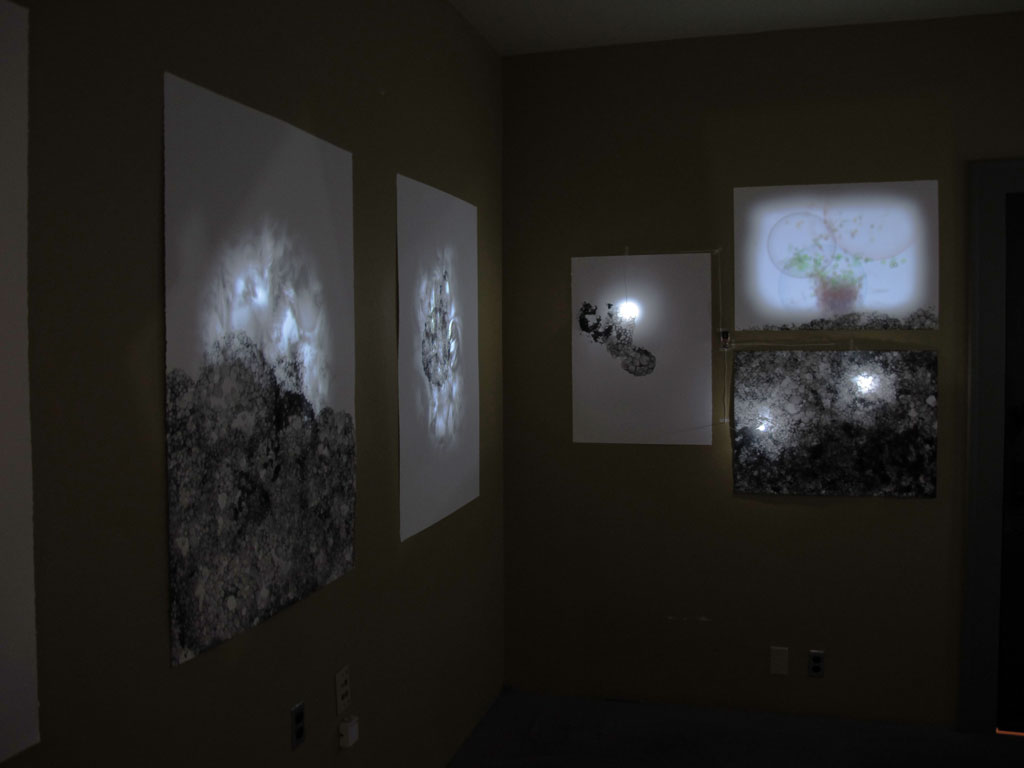
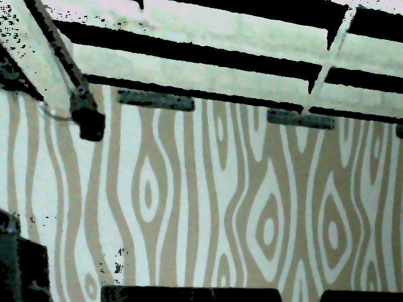
I've been using MadMapper for a while now, and it certainly saves a lot of time and effort compared to my home-brew solution that I'd been using before.  One of the amazing things that MadMapper can do is what is known as "spatial scanning." The result of a scan usually looks something like this:

union pine (original)

union pine (original)

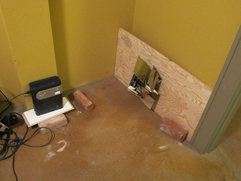
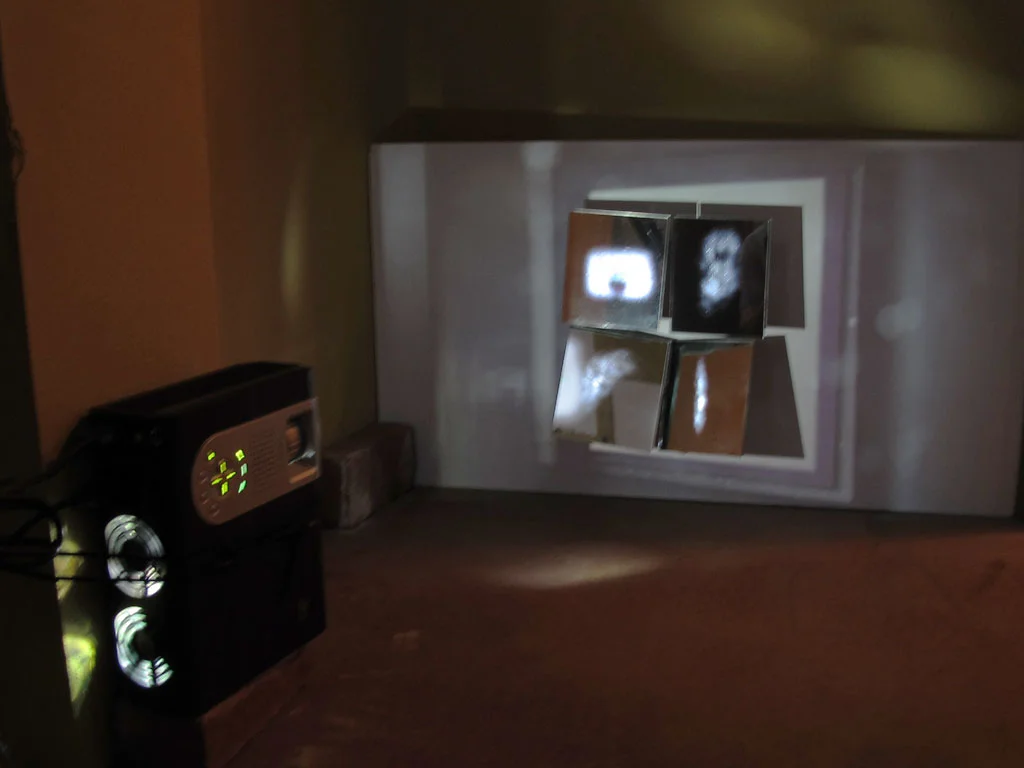
It works by using a camera connected to your computer to capture the scene while projecting a series of black and white bands.  The bands are captured by the camera, processed, and the result is a recreation of the scene as it appears from the perpective of the projector lens.  You can then use the scanned scene as a background image in the MadMapper UI and simply line up all the projection shapes according to the image (rather than having to watch the physical projected scene while dragging points around).

While amazing, the spatial scanner often yields a very grainy image.  For complex mappings this can be a little tricky to work with. After watching a tutorial video that illustrates a technique to fill in the missing pieces of the image using some photoshop filters, I decided to take a crack at making an automated tool to patch up the spatial scanner output.

In the end, I came up with two ways of processing the scan images, one is a photoshop macro, the other is a processing sketch.  They both have some specific strengths and weaknesses, but so far the processing sketch tends to sharpen up the areas of the image that are most important to me when doing projection mapping: details and edges.

Here's a scan of stage at Union/Pine.  Both photoshop and the processing sketch handle this one pretty well.  Processing wins out on the details of the back wall.

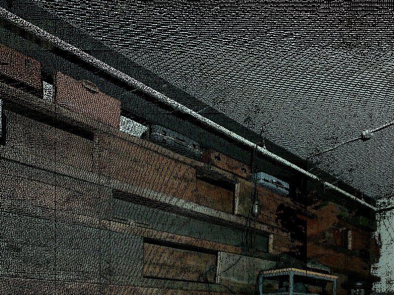
Here's a scan of the stage at the Doug Fir, processing fills in more of the voids, but the borders are a little smoother with the photoshop filter.

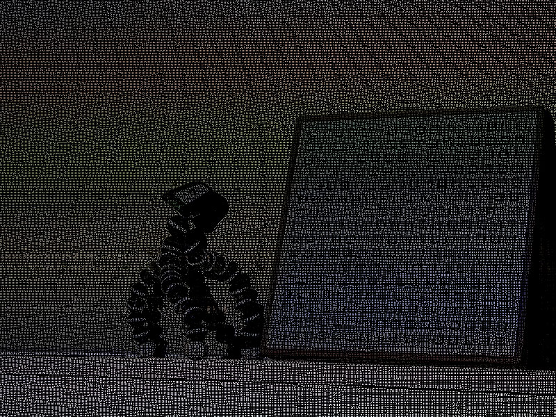
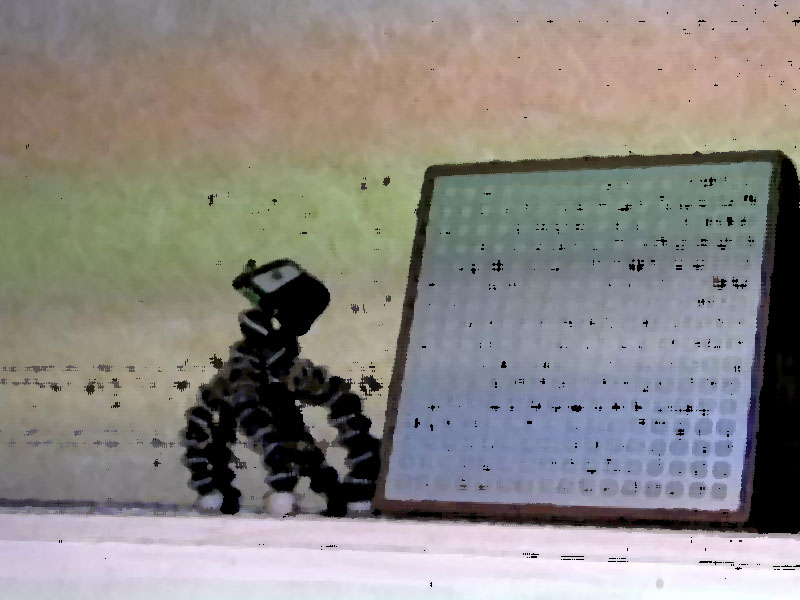
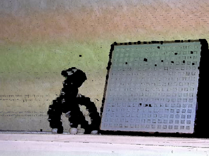
Still life, a gorillapod and a monome.  The legs of the gorillapod are better defined with the photoshop filter, but the processing sketch yields better details in the monome buttons.

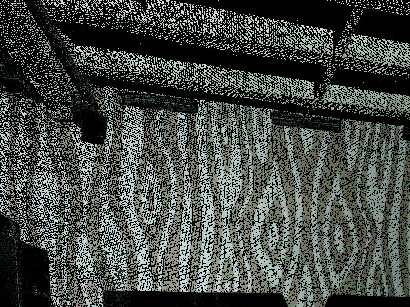
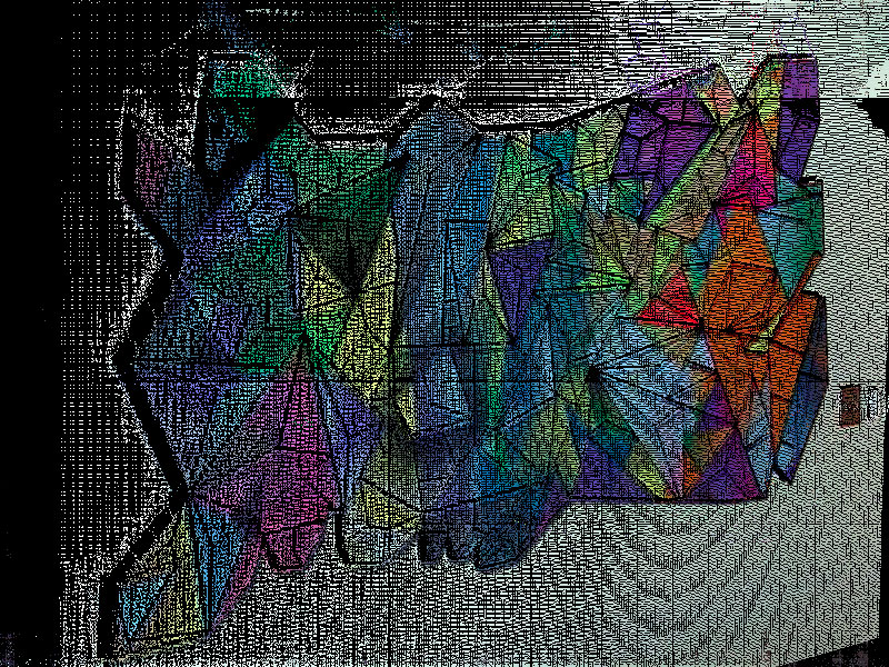
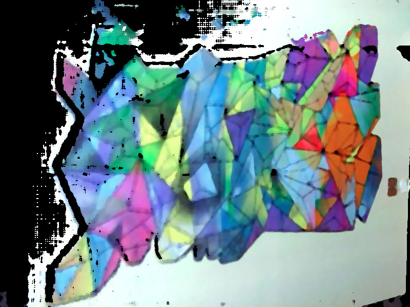
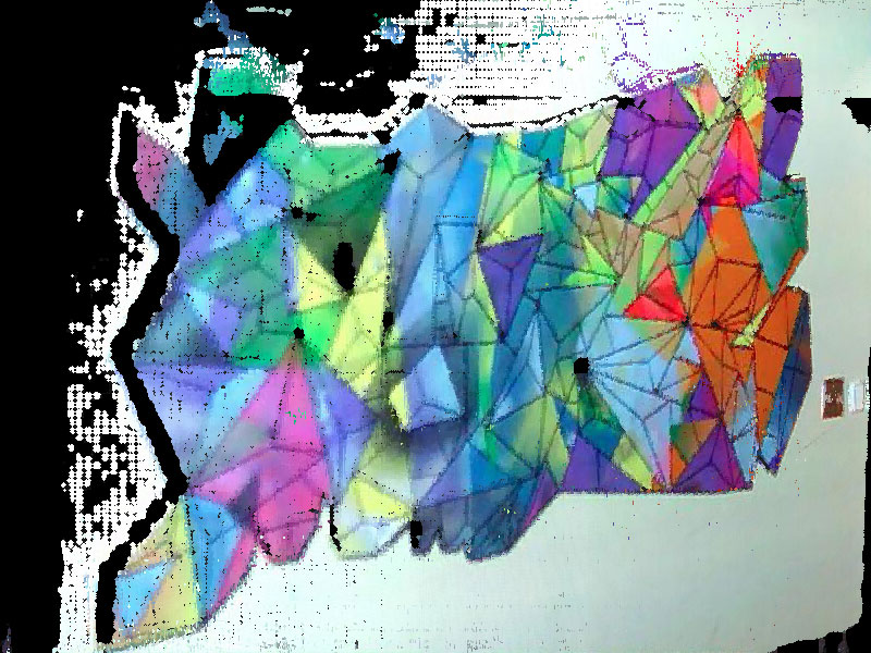
A painting.  Processing sketch wins this one quite handily, the edge detail is much clearer between the colored polygons.

As I said, it's kind of a toss-up for these two tools. I'll keep using both and pick whichever produces the best result for the task at hand.

I'm still working on the processing sketch but will release it once I get it working as a stand-alone utility (it currently requires code tweaks for each usage).

If you have photoshop, you can download the macro here.

in which I go insane, make quarter scale NES cartridges by hand

I've recently been playing with a local band called Emulator.  We do covers of old Nintendo game music and I play the projector (meaning I do all the projected video effects).  The music is great, and I get to try out all sorts of fun projection mapping ideas.  There will probably be a blog post about that at some point so stay tuned..

In any case, I had this idea to create little Nintendo cartridge key chains to give away or sell at shows. The project went through several different iterations, and ended up becoming quite the elaborate.  It went a little something like this...

Prototyping!

Before getting into the actual manufacturing, I figured I should know what I needed to make.  I started by measuring and mocking up a cross section of a nintendo cartridge in Illustrator, and printing it out in a few different sizes.  After that I used the printed images as a template and cut foam core pieces to use as mock ups.  I put them on a chain and carried them around on my keys for a few days to see how the different sizes felt in my pocket and on my keychain.  This was very valuable because I was leaning towards the larger size until I found it to be bulky and awkward.

Manufacturing

First idea, LASERS!

Back when I was playing with Son of Rust, I made a bunch of laser cut keychains that looked sort of like those translucent chips they're always fiddling with to reconfigure the ship computer in Star Trek the Next Generation.  I figured I could do something similar with opaque gray plexiglass and it'd look something like a NES cartridge.  This ended up being a bust because I couldn't find gray plexiglass, and after looking into it the price to make each keychain was just a little too high to make sense.

Second idea, 3D PRINTERS!

This seemed like a viable solution, but the output of extruded 3d printers still has a pronounced grain from the plastic filament.  This can be solved by tooling the finished piece but would mean a lot of manual labor for each part.  Since I don't have a 3d printer yet, I'd have to have that work done by someone else so the cost was again an issue.

Final idea, resin casting!

Casting copies of a tiny cartridge using a silicone mold and some polyurethane resin seemed like a good solution, the cost was unbeatable (only about 15 cents worth of resin per part).  However, I'd never done any casting or mold making before and I still needed a master model to create the mold.

Rather than order a 3d printed model, I took on the task of manually milling one from jewelers wax using a miniature drill press and X/Y stage.  This was done entirely by hand and I now have a huge appreciation for CNC machines..  I used a 0.05 inch dremel cutting bit, and a 0.025 inch engraving bit and manually milled off the wax using the X/Y stage in multiple passes like an etch-a-sketch.  I spent some time with my dial calipers and a full scale cartridge to keep the proportions right, but most of it was done ad-hoc.

Originally I was just going to add the major physical features but once I had a few of the small details added I realized I had to go all the way so I put the recessed areas in the back, screw holes, and even the little grip marks on the sides.  I'm glad I went to the trouble because they came out looking great.

After I had the wax model finished, I was ready to make a mold. The first couple of molds worked ok but it became clear that some of the physical parts of the model were too thin and didn't cast well.  Also the tooling marks on the cartridge were quite pronounced which I didn't like.  I sanded off the tooling marks, and made a couple additional molds which are now operating like a tiny factory in my work shop.


Labels

You can't just have a blank cartridge.. How would you know what game it is!?  In the interest of keeping things authentic, I studied the label designs of a hand full of classic games.  There are a lot of games released early in the platform's life that have very consistent label design, so I used that design aesthetic as a guideline.

Borrowing the design language of those original cartridges I came up with two custom label designs with musical themed artwork. No Limits PDX were able to print my designs and cut the 0.025 inch radius into the corners.  They have a fancy printer that can both print and cut on adhesive backed vinyl stock.  They were able to get nice full bleed prints with a very precise edge.

Finished!

So, here they are.  Many hours of work and lots of learning went into this project and it turned out way better than I was expecting.

Now I just need to take them to a show and see if anybody wants to buy one..

driving an RGB LED matrix

For quite some time I've been interested in getting a good RGB matrix circuit figured out.  I've used the max7219 to do a one-bit 8x8 matrix, but the idea of being able to drive full color video is an intriguing challenge.  After a freelance job inquiry came in regarding RGB LEDs driven by an Arduino, I figured it was about time to get that all figured out. So far, I've built one circuit using a cascade of shift registers.  Three of the 8-bit registers handle each color, and one handles the common anode to do row-scanning.  An Arduino is driving the circuit by way of a hardware timer, and is continuously strobing the entire set of shift registers, turning individual colors on and off to create manual pulse width modulation.

It's working pretty well, the flicker that you see in the video isn't visible to the human eye.  However, due to the relatively low clock speed of the Arduino, only ~28 steps of brightness are possible which creates a fairly limited color space.  There's also not much head-room left on the Arduino for communication and display logic.

This circuit would be handy for a simple ambient display of some kind but I'm going to start over and try using some TLC5940's instead.  They interface via SPI and send out PWM on 10 pins with a resolution of 1024 steps which blows my current PWM resolution out of the water.  Plus, the SPI interface shouldn't be as taxing on the Arduino so I'm hopeful I can get it set up to receive and decode video at nice frame rates.

I'll post more once I have something working on my breadboard..

projecting onto mirror arrays

This March I was fortunate enough to be invited to participate in a three night event put on by Liminal as part of the March Music Moderne event in Portland.  In addition to providing projection mapping for "Capital Capitals," I worked with Bryan Markovitz to create an installation piece based on Gertrude Stein's novel "The Making of Americans." 

The installation included some custom software that I wrote which would drive projected content.  This content would be projected onto several large pieces of art hanging from the walls of the room.  This all seemed straight forward until we saw the room..  It was approximately the size of a shoe box, meaning my projector would only yield about a four foot wide image.  This gave us very little flexibility for placement of the artwork since all the projected content would end up being constrained to a very small portion of the space.  I was not happy about this.

The most obvious solution I could think of was to use a single large mirror to increase the throw distance.  After testing this idea it only added a marginal increase to the projection size, and due to the already limited space the physical setup was quite bulky. The idea of using a mirror stuck with me though.  If a single mirror works, why not use several small mirror panels, each one aimed at a different location in the room?  Thus was born the idea of an adjustable mirror array.

First I tested out the concept at home with a couple of mirrors, and once I was convinced that my projection mapping software worked through a mirror I set about building the adjustable mirror array.  The array is a set of four small (about 5" square) mirror panels mounted on brackets I made that allow the mirror to swivel horizontally or vertically.  The biggest downfall of this system is trying to drag the control points around when all the mouse movements are reversed.

The final installation included four projected regions spanning three walls of the small room with an almost 180 degree spread around the space.  Being able to project at such strange and diverse angles created a very nice effect since it removed the projector from the experience.  In most cases, it's simple to visually track back from the wall and notice the source of the projection, but when the projector is tucked over in the lower corner of the room the projected regions seem to float on the walls as if by magic.

Rapunzel, Rapunzel, let down your.. verlet physics simulation?

Recently I was commissioned to create motion graphics for Northwest Childrens Theater to be used in a production of Rapunzel. The set features a large projection screen for scene-setting rather than having physical set pieces (the play is a pop-rock musical and most of the set resembles a stadium concert stage). Among the challenges of creating dynamic animated content, a major aspect of the show is to display Rapunzel's hair as it's deployed from the tower window. http://vimeo.com/35366140

The script calls for the hair to be let out and pulled back up many times so I didn't want to use a single animation as it would become quite repetitive after seeing it for the second or third time. Like the rest of the motion content in the play I decided it'd have to be a dynamic system rather than a pre-rendered video.  Using processing, I hacked out several tests before I had what I wanted.  Once I was happy with the motion I integrated the resulting code into the larger eclipse project that I had been working on for the rest of the performance.  Here's a little review of where I started and the progression from concept to final implementation.

Before writing code I spent a few minutes drawing out what I was aiming for.  My rough idea was to position a bunch of image segments along a bezier curve.  By adjusting the offset of each segment along the curve I could then animate the hair to make it look like it was being lowered from the window.

Planning!

Before writing code I spent a few minutes drawing out what I was aiming for. My rough idea was to position a bunch of image segments along a bezier curve. By adjusting the offset of each segment along the curve I could then animate the hair to make it look like it was being lowered from the window.

Test 1 : Segmented bezier spline

The first test was to get a series of connected nodes moving along a bezier spline. This would later become the basis for drawing a series of hair segments aligned along the path.

Test 2: Images aligned along a bezier spline

Next, I added some code to draw images at each point in the segmented path. The angle of each image is calculated via atan2 using the coordinates of the target point and the neighboring point. The results worked well but started to look funny when the curve was more extreme since the joints between each image became very obvious.

Test 3: Drawing a single textured mesh

The previous technique worked when motionless but when animated it looked sort of like links in a chain rather than a contiguous braid of hair. I also wanted to be able to use a single image of hair rather than ask the illustrator, Caitlin Hamilton, to draw a bunch of individual segments. This turned out to be easier than I thought since I already had the code done to figure out the angles of each segment. Vertices are positioned perpendicularly on each side of a segment and the mesh is drawn from end to end as a single quad strip.

At this point I felt like I was getting close to finished, but the motion of the hair really didn't feel right. I added some random movement to the bezier control points so the hair would appear to sway, but the extending motion along the path had an unnatural and sort of creepy look to it. This lead to something I thought of in my initial brain storming, but had dismissed as overkill.

Test 4: Verlet physics simulation!

The last test was more of a complete re-do than an iterative development. Rather than use a bezier curve, I decided to go for an actual physics simulation of linked nodes. Thanks to toxiclibs this was a fairly simple task, and fortunately I was able to use a bunch of the existing code to calculate segment angles and build the textured mesh for rendering. As soon as I saw it in motion it was obviously the superior solution.

This final test worked great and I quickly set about integrating it into the performance tool. The deploy/retract animation is achieved by raising and lowering the top end point of the verlet particle string. There are also some invisible constraints which guide the particles making it look like they’re moving out and over the window sill (shown as red shapes in the above screen shots). It sure seemed like overkill when I though of this but I’m really glad I gave it a try. The results are exactly what I was shooting for in the beginning, and after lots of testing I’m fairly sure the physics won’t glitch out and ruin the show.